- 您现在的位置:买卖IC网 > Sheet目录311 > AS3647-ZWLT (ams)IC LED DVR 1600MA FLASH 13WLCSP
AS3647/47B
Datasheet, Confidential - D e t a i l e d D e s c r i p t i o n
1. R/sC = Read, self clear; after readout the register is automatically cleared
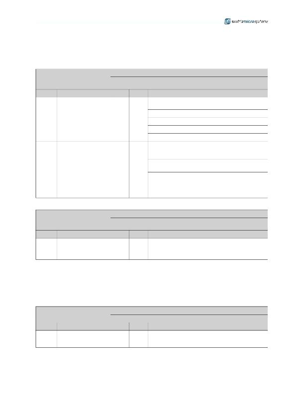
Table 15. PWM and Indicator Register
PWM and Indicator Register
Addr: 9
This register defines the PWM mode (e.g. for indicator) and 4/1MHz mode
switching
Bit
Bit Name
Default Access
Description
Define the AS3647/47B PWM with 31.25kHz operation for
indicator or low current mode ( mode_setting =01)
00
1/16 duty cycle
1:0
inct_pwm
00
R/W
01
2/16 duty cycle
10
11
3/16 duty cycle
4/16 duty cycle
Exact frequency switching between 4MHz/1MHz for assist
and flash modes for operation close to maximum
pulsewidth
2
freq_switch_on
0
R/W
0
Pulseskip operation is allowed for all modes -
results in better efficiency
1
In flash and assist light mode (indicator mode or low
current mode using PWM always will use pulseskip) if
led_current >=40h , the DCDC is running at 4MHz or
1MHz (pulseskip is disabled) - results in improved
noise performance;
Table 17. Minimum LED Current Register
Minimum LED Current Register
Addr: Eh
This register reports the minimum LED current from the last operation
cycle
Bit
Bit Name
Default Access
Description
led_current_min
7:0
12
00h
R
Minimum current through the current sink (only including all
current reductions as described in Current Reduction by
VIN measurements in Flash Mode excluding current
reductions caused by TXMASK )
1. As the internal change of this register is asynchronous to the readout, it is recommended to readout the register
after the flash pulse. The register will store the minimum current through the LED after e.g. a previous flash.
This current can be used for a subsequent flash pulse for a safe operating range.
2. This register is only set if an actual current reduction happens ( fault_uvlo (see page 27) =1) otherwise
led_current_min =0.
Table 18. Actual LED Current Register
Addr: Fh
Actual LED Current Register
This register reports the actual set LED current
Bit
Bit Name
Default Access
Description
7:0
led_current_actual
1
00h
R
Actual set current through the current sink (including all
current reductions as described in Flash Current
Reductions including LED current ramp up/down)
1. As the internal change of this register is asynchronous to the readout, it is recommended to readout the register
twice and compare the results.
www.austriamicrosystems.com/AS3647
1.5-4
28 - 37
发布紧急采购,3分钟左右您将得到回复。
相关PDF资料
AS3648-ZWLT-500
IC WHITE LED FLASH DVR 13WLCSP
AS3665-ZWLT
IC LED DRIVER SMARTLIGHT 25WLCSP
AS3685B-T
IC DVR PHOTOFLASH 1A 10-DFN
AS3685C-T
IC DVR PHOTOFLASH 1A 10-DFN
AS3691B-ZMFT
IC LED DVR 400MA RGB/WHT 64-MLF
AS3691B-ZTSP
IC LED DVR 400MA RGB/WH 20ETSSOP
AS3693A-ZQFT
IC LED DVR 16CH W/PWM 48-QFN
AS3693B-ZTQT
IC LED CTLR 16-CH W/PWM 64-TQFP
相关代理商/技术参数
AS3647-ZWLT-500
功能描述:IC WHITE LED FLASH DVR 13WLCSP RoHS:是 类别:集成电路 (IC) >> PMIC - LED 驱动器 系列:- 特色产品:LM3445 TRIAC Dimmable LED Driver 标准包装:55 系列:PowerWise® 恒定电流:是 恒定电压:- 拓扑:PWM,降压(降压) 输出数:1 内部驱动器:无 类型 - 主要:- 类型 - 次要:高亮度 LED(HBLED) 频率:30kHz ~ 1MHz 电源电压:8 V ~ 12 V 输出电压:- 安装类型:表面贴装 封装/外壳:14-SOIC(0.154",3.90mm 宽) 供应商设备封装:14-SOICN 包装:管件 工作温度:-40°C ~ 125°C 产品目录页面:1285 (CN2011-ZH PDF) 其它名称:LM3445M
AS3648-ZWLT
功能描述:IC LED DVR 2000MA FLASH 13WLCSP RoHS:是 类别:集成电路 (IC) >> PMIC - LED 驱动器 系列:- 产品培训模块:Lead (SnPb) Finish for COTS
Obsolescence Mitigation Program 标准包装:2,500 系列:- 恒定电流:- 恒定电压:- 拓扑:升压(升压),切换式电容器(充电泵) 输出数:1 内部驱动器:是 类型 - 主要:背光 类型 - 次要:白色 LED 频率:625kHz ~ 875kHz 电源电压:2.7 V ~ 5.3 V 输出电压:5V 安装类型:表面贴装 封装/外壳:10-TFSOP,10-MSOP(0.118",3.00mm 宽) 供应商设备封装:10-µMAX 包装:带卷 (TR) 工作温度:-40°C ~ 85°C
AS3648-ZWLT-500
功能描述:IC WHITE LED FLASH DVR 13WLCSP RoHS:是 类别:集成电路 (IC) >> PMIC - LED 驱动器 系列:- 产品培训模块:Lead (SnPb) Finish for COTS
Obsolescence Mitigation Program 标准包装:2,500 系列:- 恒定电流:- 恒定电压:- 拓扑:升压(升压),切换式电容器(充电泵) 输出数:1 内部驱动器:是 类型 - 主要:背光 类型 - 次要:白色 LED 频率:625kHz ~ 875kHz 电源电压:2.7 V ~ 5.3 V 输出电压:5V 安装类型:表面贴装 封装/外壳:10-TFSOP,10-MSOP(0.118",3.00mm 宽) 供应商设备封装:10-µMAX 包装:带卷 (TR) 工作温度:-40°C ~ 85°C
AS36490FLF
制造商:TT Electronics / IRC 功能描述:AS36490FLF
AS36490HLF
制造商:TT Electronics / IRC 功能描述:AS36490HLF
AS36490JLF
制造商:TT Electronics / IRC 功能描述:AS36490JLF
AS36491FLF
制造商:TT Electronics / IRC 功能描述:AS36491FLF
AS36491HLF
制造商:TT Electronics / IRC 功能描述:AS36491HLF
